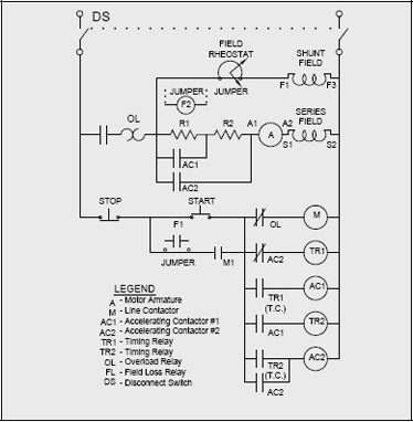
Use figure 1 if your motor has a single voltage shunt field. This type of starter cannot be used for a series machine.
Three phase motor power control wiring diagrams three phase motor connection schematic power and control wiring installation diagrams.
You can find out more Diagram below
Dc motor starter wiring diagram. Both line and wiring diagrams are a language of pictures. Wiring diagrams m c w bulletin 600 bulletin 600 manual starting switches are designed for starting and protecting small ac and dc motors rated at 1 hp or less where undervoltage protection is not needed. They show the relative location of the components.
They can be used as a guide when wiring the controller. Motor wiring diagram dc. Three point manual dc motor starter circuit diagram.
Figure 1 is a typical wiring diagram for a three phase magnetic motor starter. The disadvantage of this type of starter is that it may drop out if field resistance control is used to weaken the field for increased motor speed. Star delta y d 3 phase motor starting method by automatic star delta starter with timer.
They are operated by a toggle lever mounted on the front of the switch. The main difference between a 3 point starter and a 4 point starter is. These connections are in accordance with nema mg 1 and american standards publication 06.
Motor connections your motor will be internally connected according to one of the diagrams shown below. Use figure 2 if your motor has a dual voltage shunt field. It is not difficult to learn the basic symbols.
Figure 3 shows a four point starter circuit diagram. The internal wiring of a 3 point starter is as shown in the figure. Wiring diagrams do not show the.
The main concept behind every dc motor starter is adding external resistance to the armature winding during starting.


0 comments:
Post a Comment